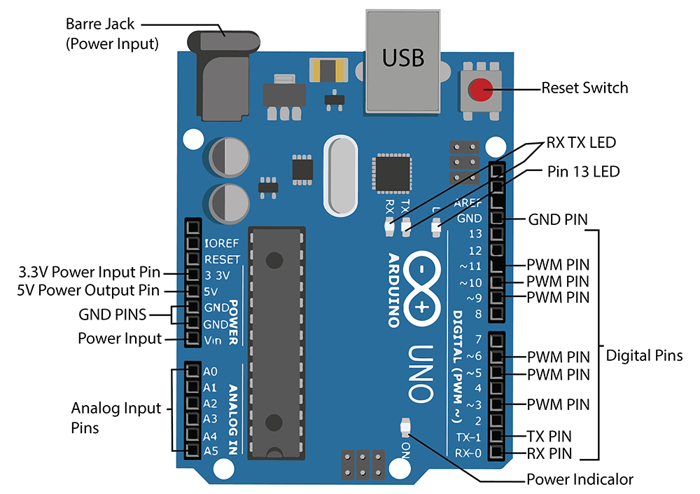
Different Parts of Arduino Uno Board
In this topic, we will go through different hardware components of an Arduino Board. Arduinos have the majority of the components in common.
Power
Every Arduino board needs a way to be connected to a power source. The Arduino UNO can be powered three ways:
- Barrel Jack – The Barrel jack, or DC Power Jack can be used to power your Arduino board. The barrel jack is usually connected to a wall adapter. The recommended voltage for most Arduino models is between 6 and 12 Volts.
- VIN Pin – This pin is used to power the Arduino Uno board using an external power source. The voltage should be within the range mentioned above.
- USB cable – when connected to the computer, provides 5 volts at 500mA.

Pins
The pins on your Arduino are the places where you connect wires to construct a circuit (probably in conjunction with a breadboard and some wire). The Arduino has several different kinds of pins, each of which is labeled on the board and used for different functions:
- Ground or GND: These pins are used to ground circuits.
Note: The GND pins are used to close the electrical circuit and provide a common logic reference level throughout your circuit. Always make sure that all GNDs (of the Arduino, peripherals, and components) are connected to one another and have a common ground.
- 5V: This pin provides 5V Voltage to the circuits.
- Analog Pins: These pins are for reading analog voltage value from sensors and convert them into a digital value, that can be read. In Arduino Uno, there are 6 analog pins labeled A0-A5.
- Digital Pins: These pins are for both digital input (reading the state of the switch) and digital output (controlling the LED). In Arduino Uno, there are 14 digital pins (0 -13).
Alert: It’s important to note that each pin can provide/sink up to 40 mA max. But the recommended current is 20 mA and the absolute max current provided (or sank) from all pins together is 200mA.
- PWM Pins: You may have noticed the tilde (~) next to some of the digital pins (3, 5, 6, 9, 10, and 11 on the UNO). These pins act as normal digital pins, but can also be used for something called Pulse-Width Modulation (PWM). They are used as analog output (like fading an LED in and out).
- RX – TX: These are serial communication pins, used to communicate with other Arduino boards as well as computers.
Reset Button
This button is used to restart the code that is loaded on the Arduino.
Power Indicator LED
This LED should light up whenever you plug your Arduino into a power source. If this light doesn’t turn on, there’s a good chance something is wrong.
RX – TX LEDs
These LEDs will give us some nice visual indications whenever our Arduino is receiving or transmitting data on the RX TX Pins.
Pin 13 LED
Arduino Uno has an inbuilt LED connected to digital pin 13. Whenever the pin is HIGH, LED lights up and when it is LOW, LED is Off.
Conclusion
You have to remember these terminologies. We use these many times in coming lessons.


